
Beginner · about 15 minutes
Convert DXF to G-code
Browser2CAM converts a DXF drawing to CNC G-code directly in your browser. Your file stays on your device. This tutorial shows the complete workflow using demo.dxf.
Convert your own DXF to G-code ↗Open demo.dxf
Open Browser2CAM. On the start page, click demo.dxf below the main button. This loads exactly the drawing used in this tutorial.
- Click demo.dxf.
- Wait for the DXF preview and import panel.
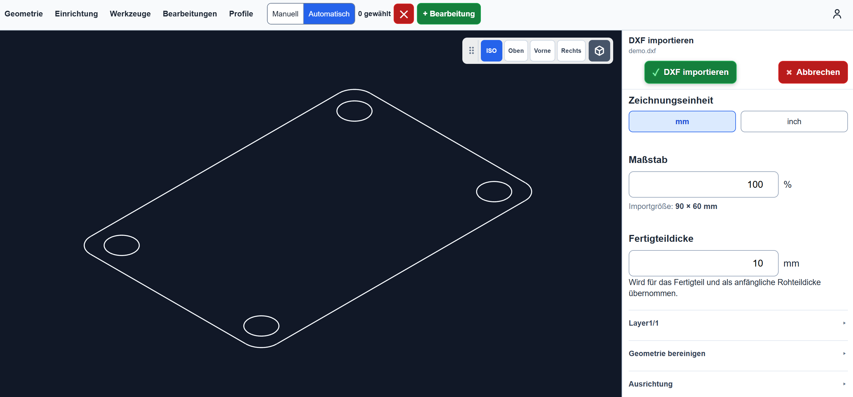
Check the DXF settings and import
Browser2CAM recognizes the drawing as 90 × 60 mm. Keep the drawing unit at mm, scale at 100% and rotation at 0°.
- Leave the drawing unit at mm.
- Check the 100% scale.
- Enter a suitable finished-part thickness for your practice stock.
- Click Import DXF.
Check the setup
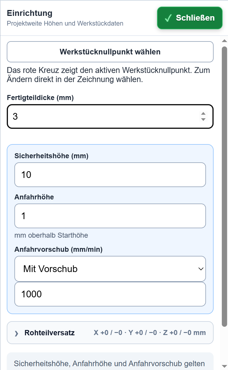
Open Setup. The finished-part thickness is carried over from the DXF import. Also verify the safety height, approach height and approach feed rate.
- Compare the finished-part thickness with your stock.
- Choose a safety height that clears all clamps.
- Adapt the approach height and approach feed rate to your machine.
- If required, choose Select workpiece zero and click the desired standard snap point.
Select the outside contour
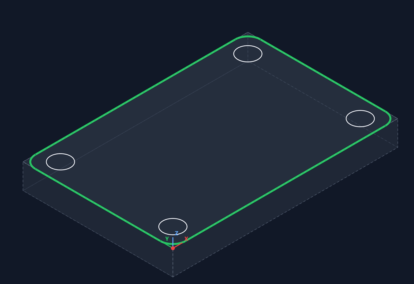
Close Setup and switch to the top view. Leave geometry selection on Automatic. One click then selects a connected closed contour.
- Select the Top view.
- Leave geometry selection on Automatic.
- Click the outside contour – it turns green.
- Check that only the required closed outside contour is highlighted in green. Use X to deselect an incorrect or no longer required geometry selection.
- Use + Operation to create an operation.

Create the contour operation
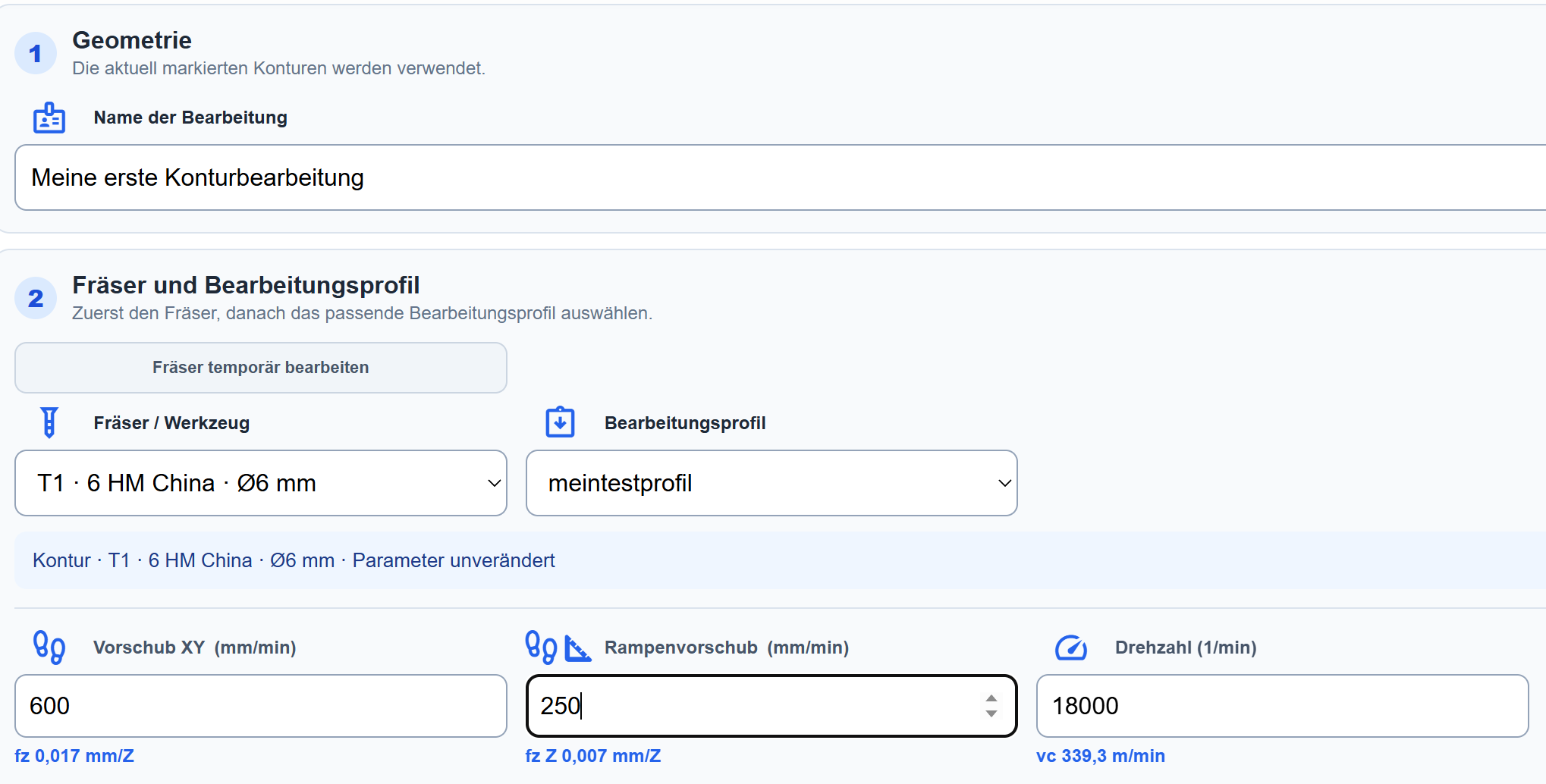
Name the operation, select a tool and enter the cutting data. This example uses a 6 mm solid-carbide end mill and the Contour operation type.
- Enter a name such as My first contour operation.
- Select the 6 mm solid-carbide end mill under Tool.
- Enter the XY feed rate, ramp feed rate and spindle speed for your tool, material and machine.
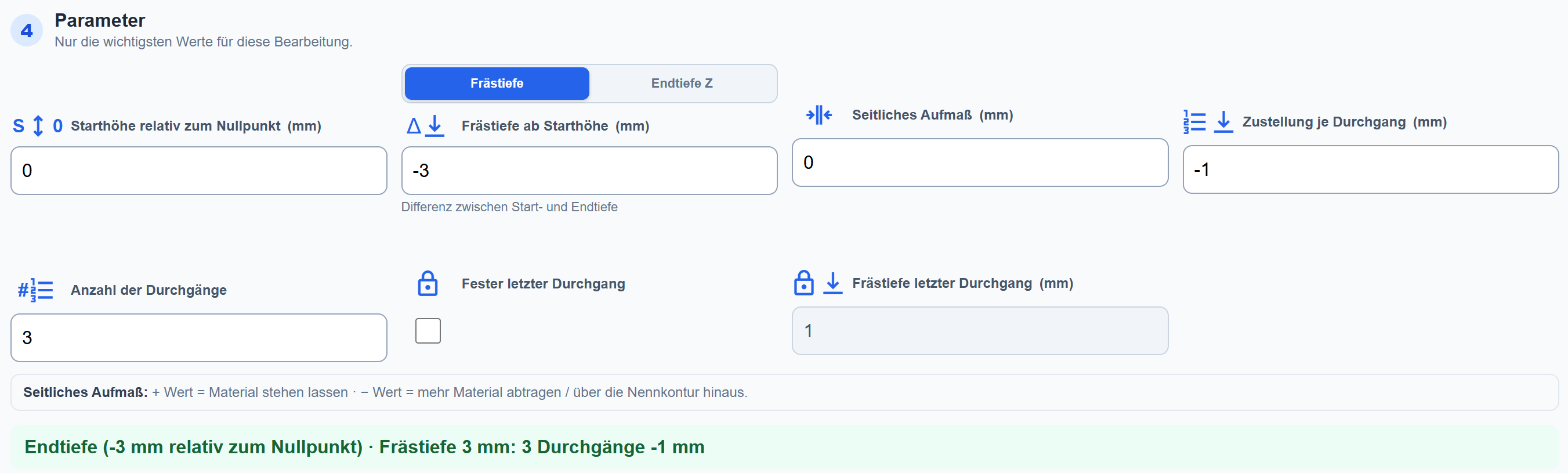
- Choose Contour as the operation type.
- Set the path side to Outside.
- Choose Ramp as the entry strategy and set a 3° ramp angle.
- Set the start height to 0 mm, the cutting depth to −3 mm and the depth per pass to −1 mm. This produces three passes.
- Finally, click Create operation.

Inspect the toolpath preview
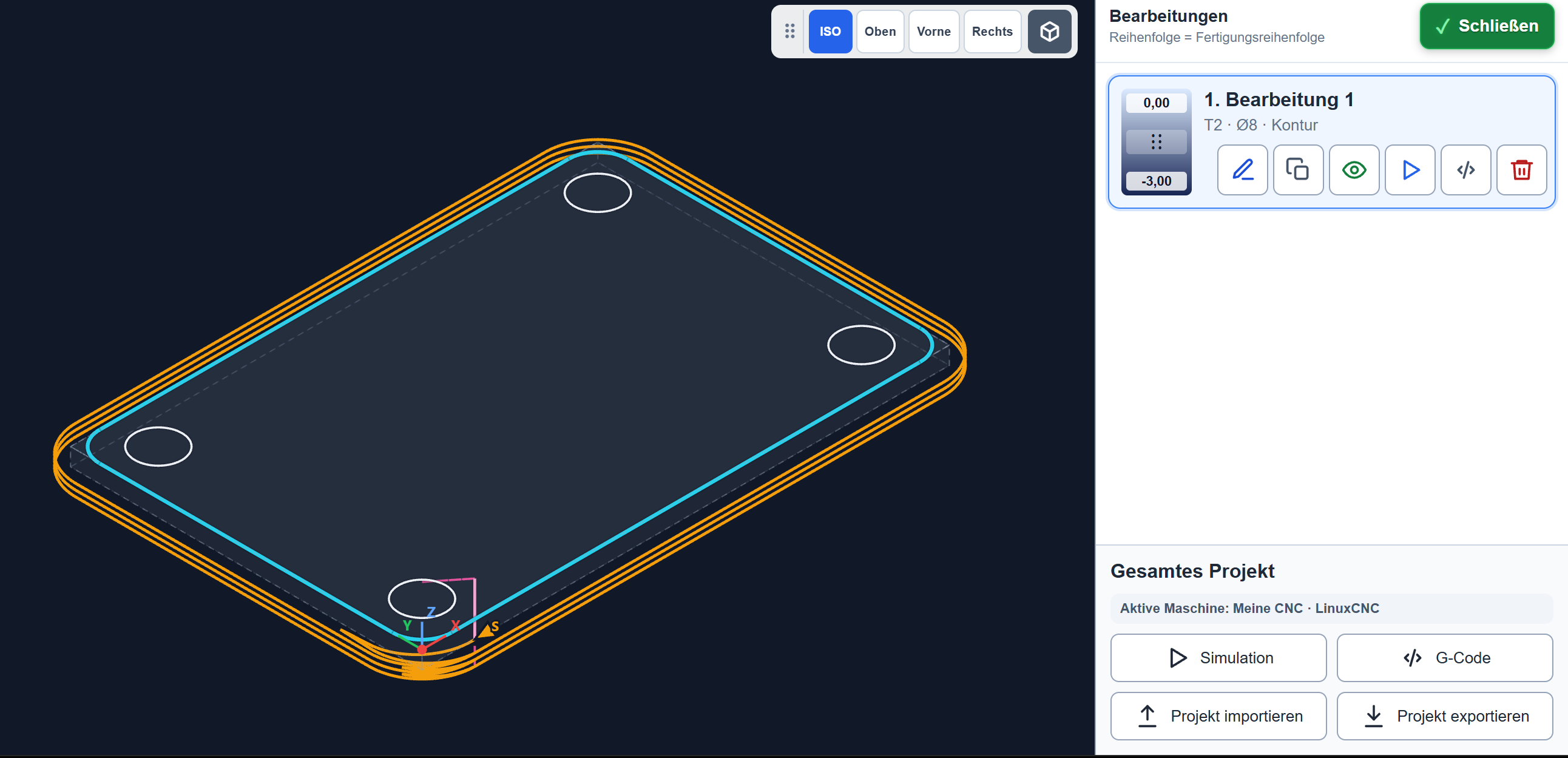
After creating the operation, a preview of the calculated toolpath appears in the workspace. The created operation is shown on the right.
- Check that the orange toolpath runs outside the contour.
- If necessary, drag the start point marked S to a suitable position on the contour with the mouse.
- Check that the panel on the right shows the Contour operation and depths from 0 to −3 mm.
- Inspect the complete path, including all three depth passes.
Simulate the operation
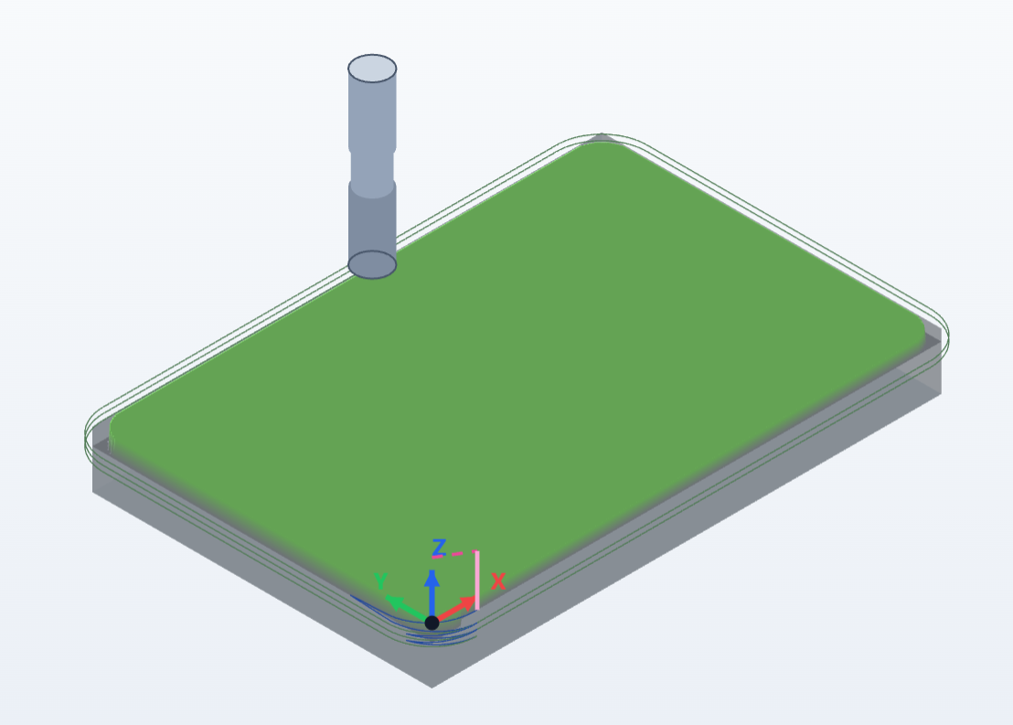
The button with the blue play symbol simulates this individual operation. It is located directly on the operation card in the panel on the right.
- Click the blue play symbol on My first contour operation.
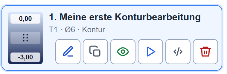
The play button on the operation card starts the simulation for this operation. - Play all three passes to the end.
- Look for collisions, unexpected linking moves and incorrect material removal.
- If anything is wrong, change the operation and simulate again.
Generate G-code
Use the button with the code symbol to generate G-code for the operation. Browser2CAM uses the currently selected postprocessor.

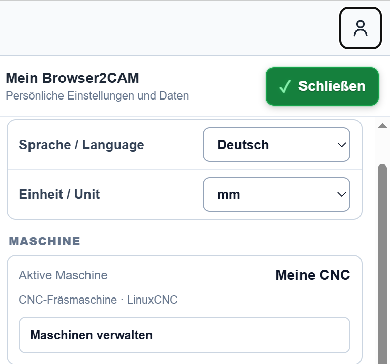
If you want to change the postprocessor, click the person icon. You can find the settings under Manage machines.
Done – final checklist
- Correct machine and postprocessor are active
- Workpiece zero matches the real setup
- Tool diameter, cutting length and stickout are correct
- Spindle speed, feeds and depths suit the material and machine
- The full simulation shows no unexpected material removal
- G-code has been inspected and a dry run is planned
Convert a DXF to G-code yourself
Open Browser2CAM and select demo.dxf on the start page, or import your own DXF file. This tutorial remains open in its own tab.
Convert your own DXF to G-code ↗